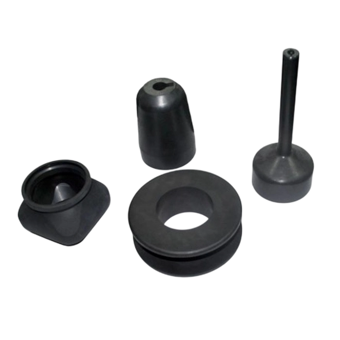
Custom molded rubber covers, boots and protective caps shield components while allowing the required movement, access or sealing function. Opening geometry, wall thickness, retention method, installation fit, material and environmental exposure should be confirmed during development. Grommets, seals, diaphragms and related products are available in our custom protective rubber parts range.

Custom molded caps and covers are built around the part they fit over. Opening shape, cavity depth, internal steps, retention features and wall sections can be defined to protect component ends, connectors, fittings and other shaped interfaces.

Closed-end cavities protect exposed component ends, studs, fittings or terminals. Opening size and internal depth are matched to the mating part.

Internal steps can follow shoulders, diameter changes or non-round sections so the cover fits the component without relying on excessive stretch.

Ribs, grooves, beads, lips or molded undercuts can be added when the cap needs a defined holding point after installation.

The opening can be sized for slip-on installation or controlled interference, depending on the component geometry and required removal force.

Wall thickness and local transitions are set around flexibility, durability, molding limits and clearance to nearby parts.

Short boot-style covers can protect deeper bodies or projecting sections where a flat cap or simple sleeve does not provide the required fit.

Define the dimensions that control how the cap goes on, where it stops and how it stays in place. Material is then selected for the heat, oil, weather or chemical exposure around the protected component.
| Product Specifications | |
|---|---|
| Product Name | Custom Molded Rubber Protective Caps & Covers |
| Category | Protective Rubber Components |
| Opening Geometry | Round, oval, rectangular or custom profile |
| Cavity Design | Straight, stepped or shaped to the mating component |
| Retention Options | Interference fit, rib, groove, bead, shoulder or undercut |
| Hardness | 30–90 Shore A |
| Sample Lead Time | About 8 Days |
| Mass Production Lead Time | 12–18 Days |
| Wall Thickness | Defined by flexibility, durability, clearance and molding requirements |
| Fit Reference | Part drawing, mating-component drawing or physical sample |
| Quality System | IATF 16949 Certified |
| Inspection Focus | Opening, cavity depth, wall and retention geometry; AQL/C=0 when specified |
| Tooling | In-house mold development with CNC machining |
| Customization | Custom geometry, material, hardness and fit requirements |

Opening fit, cavity depth and retention can be checked against the mating component before production tooling is finalized. In-house CNC machining supports custom mold development after the fit requirements are confirmed.
Typical Sample Lead Time
In-House CNC Tooling
Start with the part being protected rather than the industry name. The mating profile, opening direction, retention point and exposure determine the cover geometry.
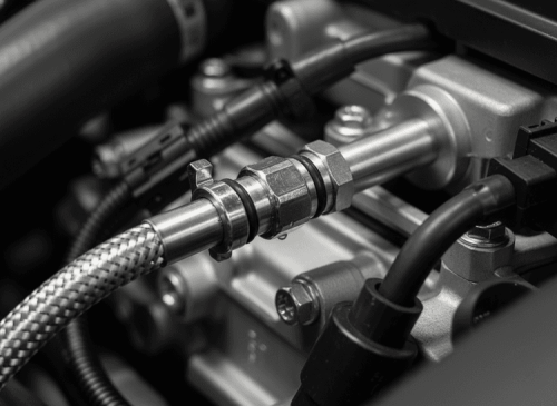
Caps can cover connector bodies, tube ends, studs or fittings. Check insertion depth, retention during assembly and nearby heat or oil exposure.
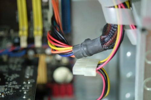
A shaped cavity can protect terminals or connector bodies while keeping clearance around wires, shoulders and adjacent components.
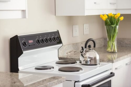
Molded covers can fit around switches, ports or component ends where the opening, cavity and grip area need to follow the housing geometry.

Removable caps can protect fittings or service points. Material grade, insertion depth and removal frequency should be defined for the assembly.

Covers for exposed connections can use a positive rib or groove when dust, moisture, vibration and outdoor handling could loosen a simple slip-on cap.

For complex molded caps and covers, fit should be reviewed against the mating component before mass production. For simple sleeves and slip-on covers, see Rubber Cover. For caps intended for food-contact use, see Food-Grade Rubber Caps.
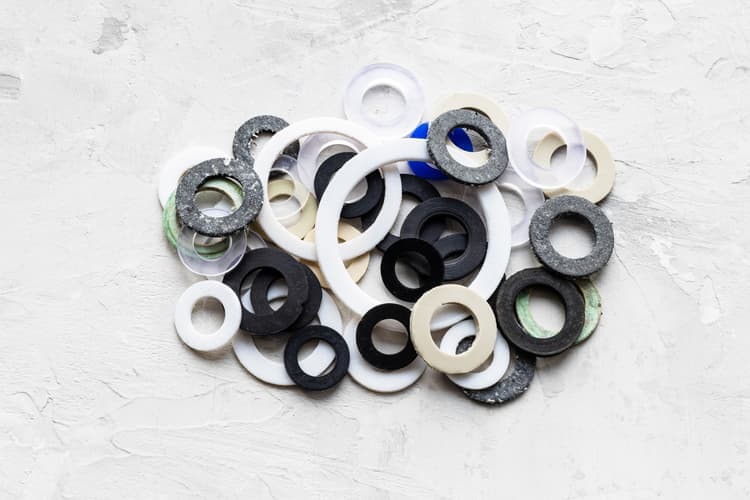
Send the cover drawing together with the mating-part dimensions or a physical sample. We review opening size, cavity depth, shoulders and required clearances.
Interference, ribs, grooves or undercuts should hold the cover without making installation or service removal unnecessarily difficult.
After the fit dimensions are confirmed, the mold can be developed from 2D/3D data or a verified physical sample using in-house CNC machining.
Inspection can focus on opening size, cavity depth, wall thickness and retention geometry. AQL or C=0 requirements can be applied when specified for the project.

Explore complementary sealing solutions from our comprehensive product catalog.
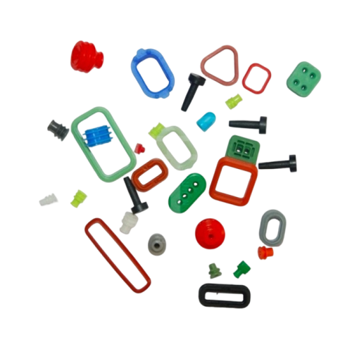

Our engineering team reviews your specs and responds within 24 hours with material recommendations and competitive pricing.