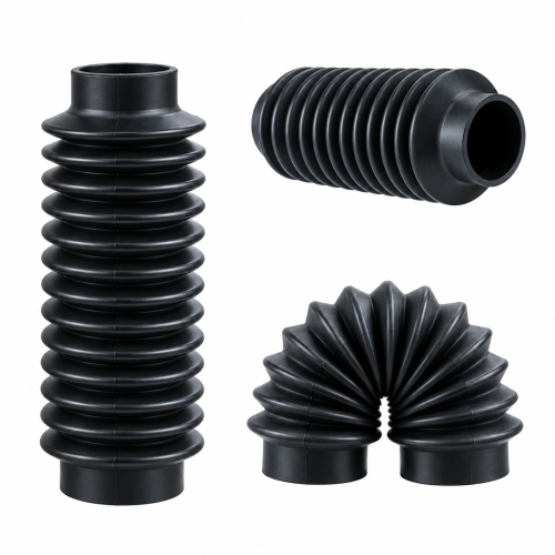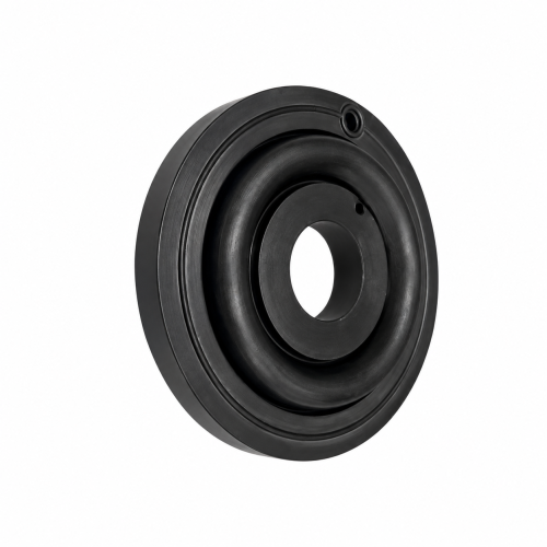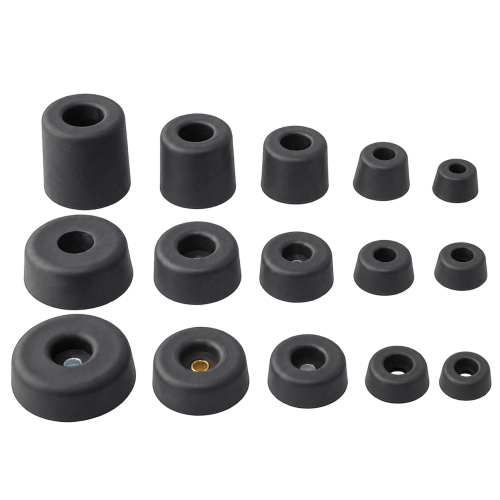
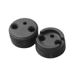
A single-wire or small-conductor panel pass-through lives or dies on tight OD tolerance and groove geometry, not on bulk cable volume. A grommet sized for a dozen-wire harness is the wrong part for one sensor lead through a thin instrument panel — the fit, retention, and tooling precision needed are different problems entirely.

Wire rubber grommets for this use case are specified from five inputs: wire OD, panel hole diameter, panel thickness, groove geometry, and strain-relief lip requirement.
| Critical Dimension | What It Controls |
|---|---|
| Wire OD | Inner clearance around the conductor |
| Panel Hole | Locating diameter that seats the grommet in the cutout |
| Panel Thickness | Groove width so the part stays seated after install |
| Groove Geometry | Retention against pull-through |
| Strain-Relief Lip | Reduces flex stress at the wire exit point |
Once those five are set, precision tolerance on the 0–10mm OD range can be held to ±0.02mm, against a ±0.10mm standard grade. Holding ±0.02mm typically calls for hardened, precision-machined tooling, which raises per-unit cost over the standard grade — worth specifying only when the installation genuinely needs that tightness, not as a default.
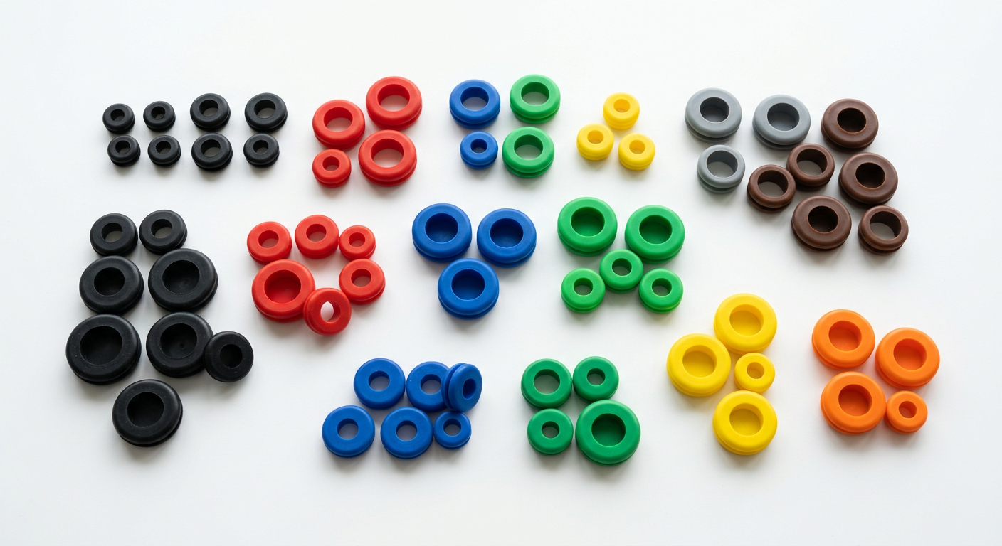
For a single-wire grommet, panel-edge fit and material consistency directly affect the rest of the assembly. Hongjie’s production systems support IATF 16949:2016 and ISO 13485:2016 certification, with controls upgraded in 2017 for automotive, medical, appliance, hydraulic and industrial OEM programs.
UL-certified materials and FDA/NSF-compliant options are also available where the application requires additional electrical, food-contact or medical documentation.
The manufacturing base includes:
This scale supports drawing-based sampling without requiring a completely new tool for every project.

Four compounds cover most small-wire exit points:
Compounds across the range are rated from –60°C to +325°C depending on selection, with resistance data checked against 500+ fluids, gases, and chemicals during material qualification.
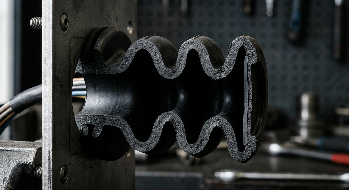
Small-wire grommet designs are reviewed in 3D CAD and can be evaluated with FEA before tooling. STEP or IGES files, drawings and marked-up samples are accepted for geometry review.
Functional prototypes are typically available in 3–5 business days after the drawing and compound are confirmed. MOQ, tooling cost and lead time depend on the part geometry and complexity and are confirmed during the same review.
For multi-wire harnesses rather than single conductors, custom wire-harness grommets provide grouped-conductor retention and support larger bend radii.


Through thin equipment covers

From control enclosures

Automotive Rubber Grommets for Wire Harnesses installation points

Instrument faceplates and panel pass-throughs
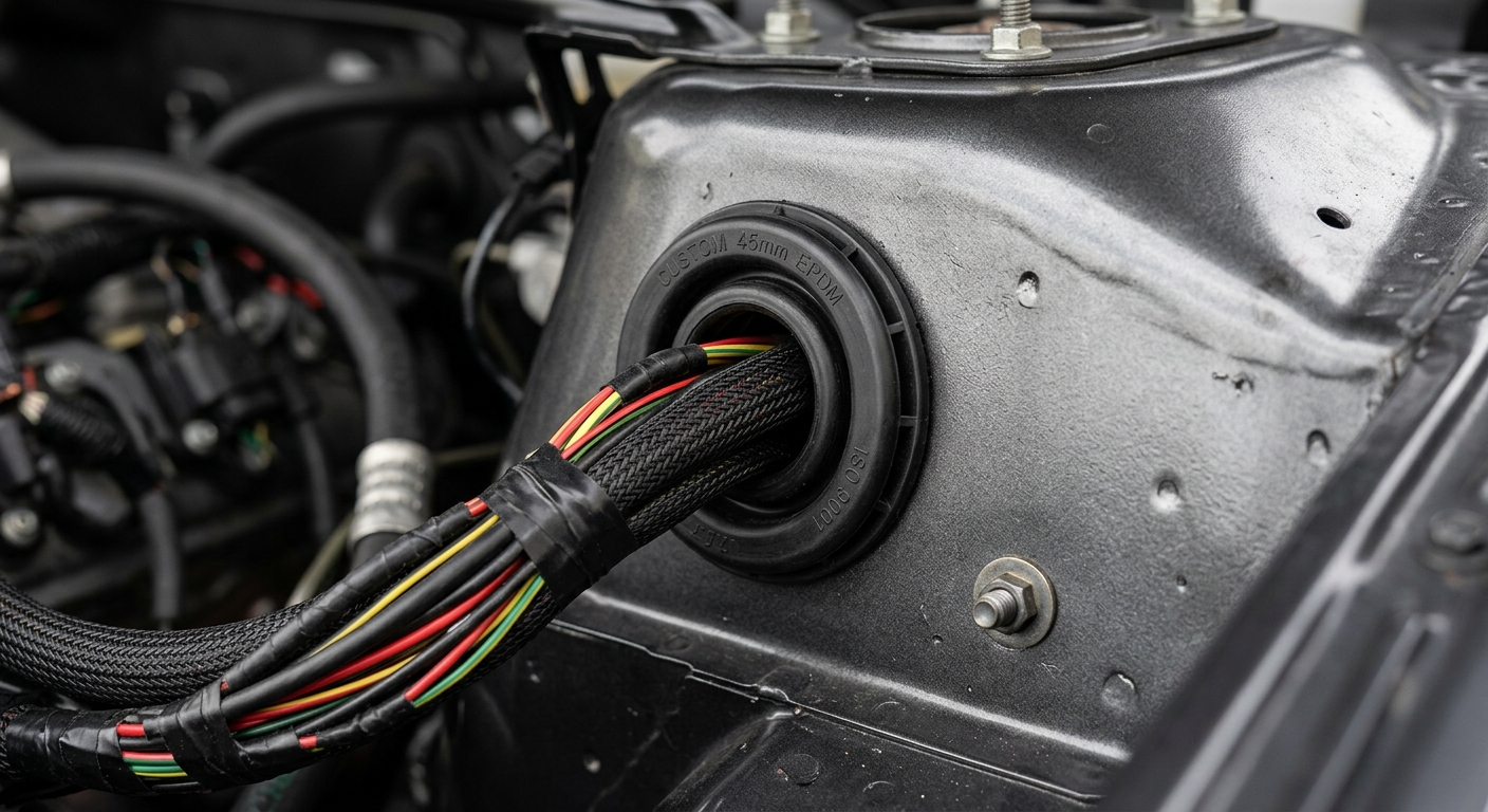
For seating a part in a bolt-hole or mounting cutout rather than sealing a wire exit, Rubber Grommet Gaskets for Mounting Holes handle that geometry. For wider cable bundles and rectangular panel openings, Rubber Grommets and Rectangular Rubber Grommets for Panel Cutouts fit those larger entries.
Where the pass-through must also seal against water or dust, custom waterproof rubber grommets add a compression lip to the standard grommet form.

Upload a drawing, panel dimensions, or an existing sample for a fit and material review. Contact Hongjie's engineers to start the drawing review before sample tooling.

Explore complementary sealing solutions from our comprehensive product catalog.