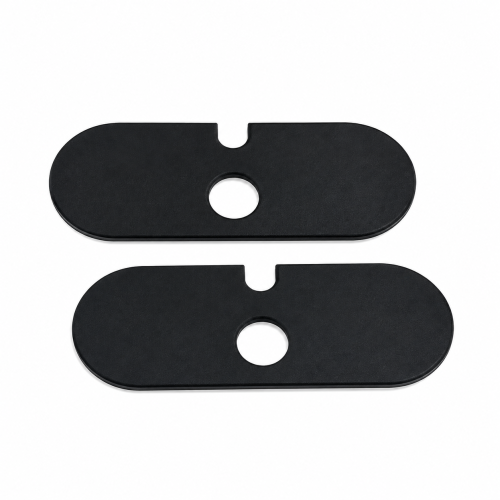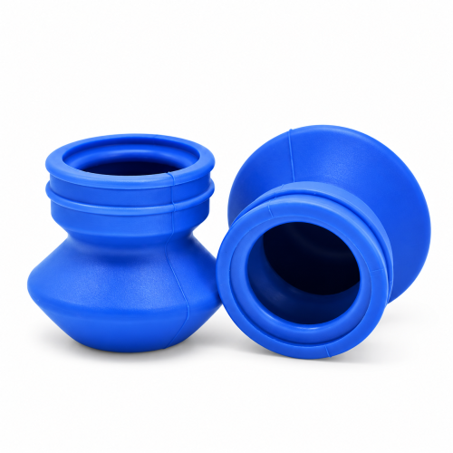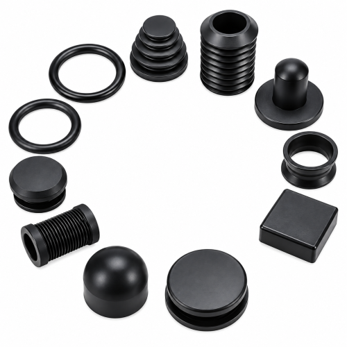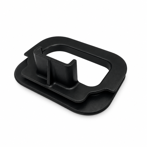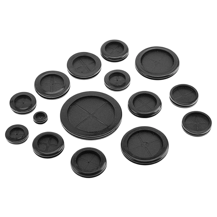
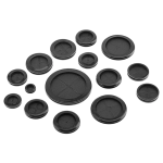
Cable rubber grommets seal and protect the point where a thick cable or a full wire-harness bundle passes through a metal or plastic panel. They're built for OEMs and panel builders who need the bore, groove, and flange matched to a specific cable envelope and panel thickness — not a bin of loose stock sizes. Send the cable OD, panel hole, and panel thickness, and the groove/flange geometry follows from there.

Five core dimensions control whether a cable grommet seats correctly and stays retained under vibration or pull.
| Dimension | What It Controls |
|---|---|
| Cable / Bundle OD | Bore size — fits the actual envelope without pinching the jacket |
| Panel Opening | Hole diameter or cutout the grommet must seat into |
| Panel Thickness | Groove width — too loose and the grommet walks out of the hole |
| Groove Depth | How firmly the grommet locks onto the panel edge |
| Flange OD | Coverage on each side of the panel |
Dimensional precision on the bore and groove holds to the following tolerance bands:
| Dimension Range | Standard Tolerance | Precision Tolerance |
|---|---|---|
| 0–10mm | ±0.10mm | ±0.02mm |
| 10–25mm | ±0.15mm | ±0.05mm |
| 25–50mm | ±0.20mm | ±0.08mm |
| 50–100mm | ±0.25mm | ±0.10mm |
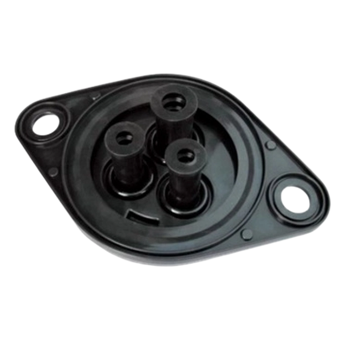
Choose the grommet design according to the cable layout and panel opening:
Multi-bore designs require more tooling work because each bore must maintain its own sealing line without weakening the material between openings. They are worthwhile when routing individual wires through separate holes is impractical.
Material selection drives heat, oil, and weather performance more than the grommet shape does.
| Material | Typical Duty | Typical Continuous-Service Range |
|---|---|---|
| EPDM | Outdoor panels, ozone and weather exposure | −40°C to +120°C |
| NBR | Oily or greasy machinery environments | −30°C to +100°C |
| Silicone | Wide temperature swings, compliance-grade needs | −60°C to +200°C |
| Neoprene | General abrasion and mild chemical exposure | −40°C to +100°C |
Hongjie’s compound library covers service temperatures from −60°C to +325°C for specialty applications. A close cable-to-bore fit can limit dust and light splash, but this does not represent a certified ingress rating.
For defined water-ingress protection, custom waterproof rubber grommets use a continuous sealing lip rather than relying only on cable-to-bore friction.
Automotive and appliance harness bundles can use custom wire-harness grommets sized to the OEM firewall or housing drawing. For wider temperature requirements or compliance-grade materials, custom silicone rubber grommets for cables use the same groove-and-flange design approach.
Cable grommets are produced by injection or compression molding from customer drawings, with in-house tooling for non-standard bores, grooves, and flange profiles. CAD files in STEP or IGES format support the drawing-to-quote process.


Route through firewall and body panels using Automotive Rubber options.

Take power and control cable entries into sheet-metal cabinets.

Route power cords or internal cable groups through molded or metal enclosures.

Carry cable routing across machinery guards and outdoor housings.
| Standard | Scope |
|---|---|
| IATF 16949:2016 | Process control for automotive harness and firewall grommet programs. |
| ISO 13485:2016 | Quality documentation for medical device cable entries. |
| UL certification | Safety compliance for electrical panel and cabinet cable entries. |
| FDA/NSF-compliant materials | Compound options for appliance and food-adjacent equipment housings. |
Dimensional and material consistency are held using SPC and Six Sigma methods, targeting Cpk > 1.33.
Email your drawing and specs through our contact page for a drawing review. Include:
Functional prototypes follow within the timeframe below once tooling is approved:
| Cable/Bundle OD | Panel Thickness (typical) | Flange OD | Prototype Lead Time |
|---|---|---|---|
| 6–10mm | 0.8–1.5mm | Sized to drawing | 3–5 business days |
| 10–20mm | 1.0–2.5mm | Sized to drawing | 3–5 business days |
| 20–40mm | 1.5–3.0mm | Sized to drawing | 3–5 business days |
| 40mm+ / multi-bore bundle | 2.0–4.0mm | Sized to drawing | 3–5 business days |
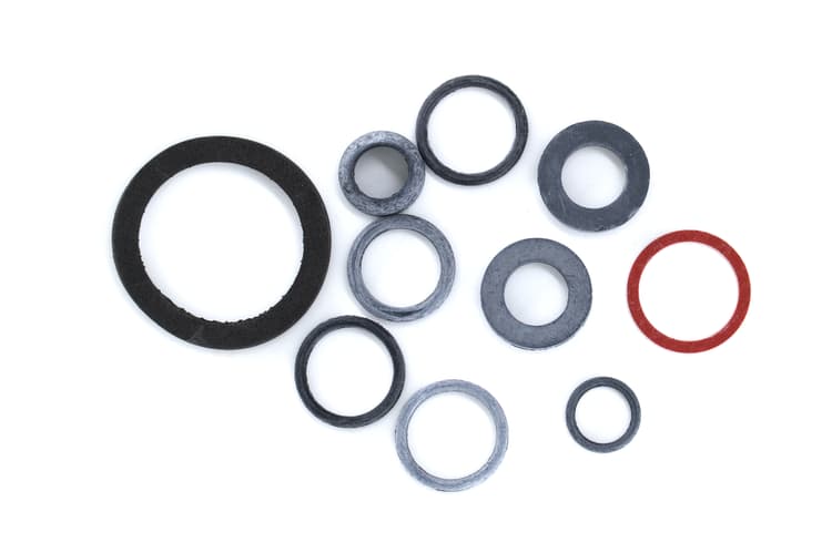
For outdoor, wet or ozone-exposed panels, EPDM rubber grommets are the material-specific option.
Enclosure lids, doors and housings that must keep water out are covered under waterproof rubber seals.


Explore complementary sealing solutions from our comprehensive product catalog.