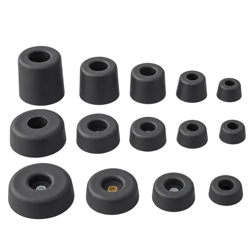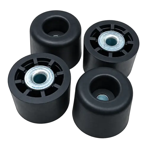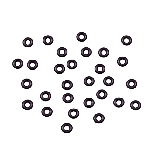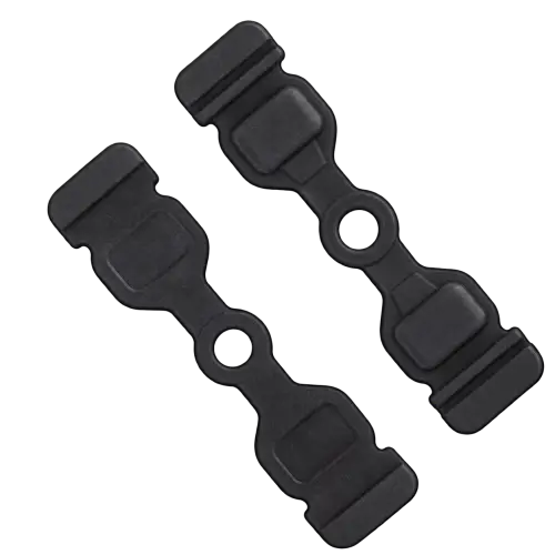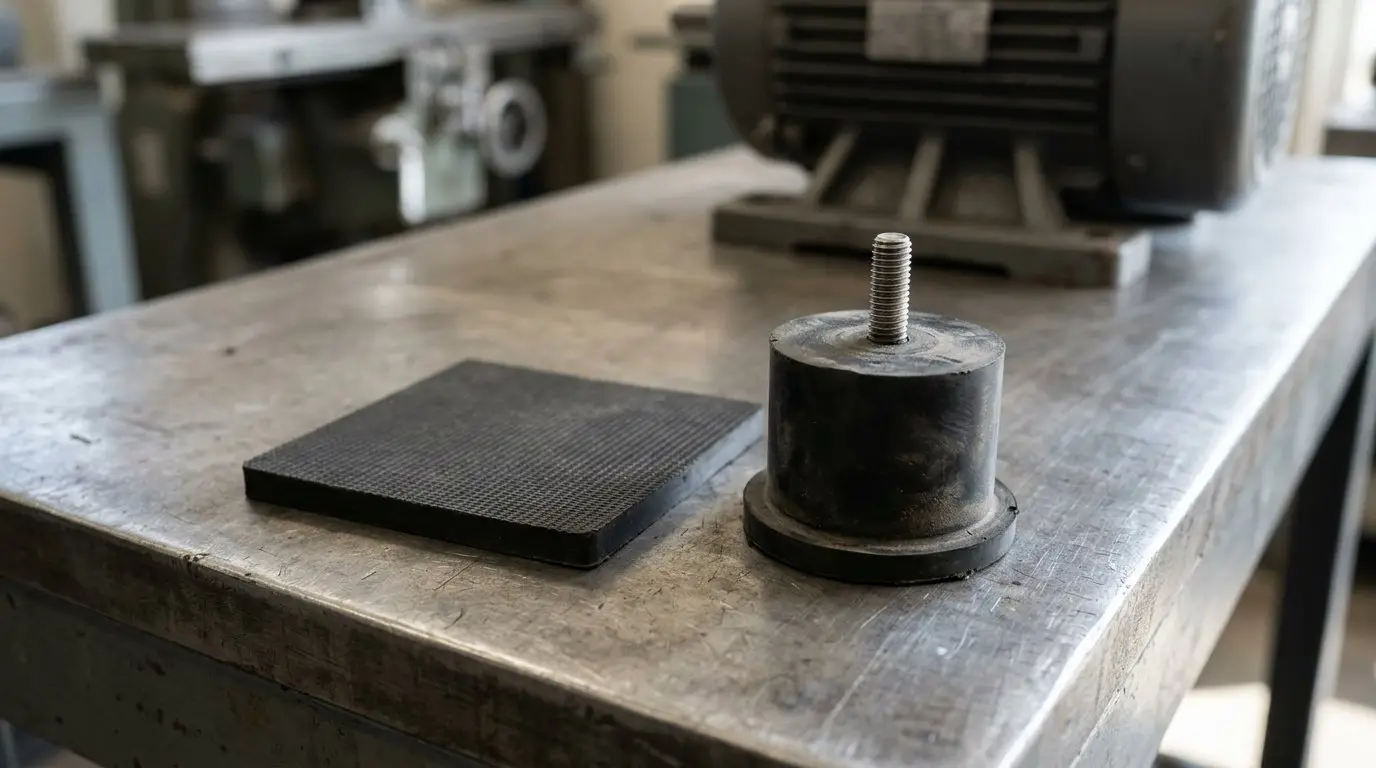
The mounting interface decides the form before material ever enters the conversation: if the machine sits on a flat foot and the load always pushes down, a pad works and is the cheapest answer; if the load can reverse, the machine must be positively attached, or the isolator has to carry shear and lateral load as well, you need a bonded stud or bushing mount. Pick the form from the load path and the bolt pattern, then size it by load per mount and required static deflection, not by catalog appearance. This guide works that sequence in the order you actually face it, starting from the drawing in your hand and ending with a spec sheet you can send out.
Key takeaways
Bolted machinery rarely offers a free choice of isolator. The foot, the frame hole or the tapped boss is already there, and it physically decides which forms can attach. Answer three questions about that interface and the shortlist drops to two or three shapes before anyone mentions NBR or neoprene.
| Form | Load directions | Retention | Softness | Typical fit |
|---|---|---|---|---|
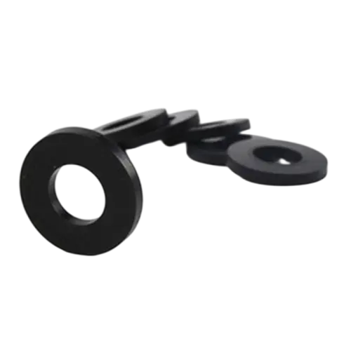
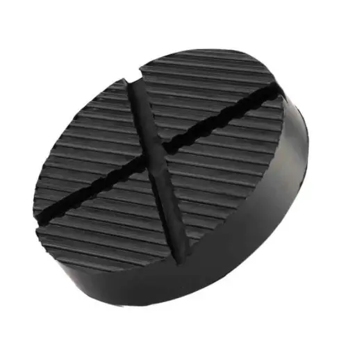
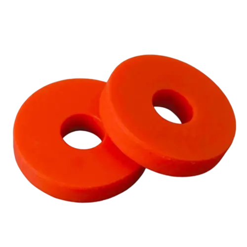
| Flat pad | Compression only | None | Medium | Fans, panels, enclosures |
| Plate-and-pad | Compression, light shear | Partial | Medium | Compressors on rails |
| Bushing mount | Shear plus compression | Yes | Soft | Pumps, machine tools |
| Studded mount | Compression, tension, shear | Yes | Soft to medium | Motors, gensets |
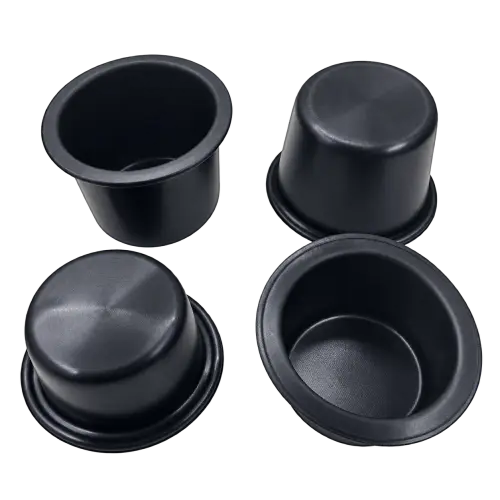
| Foot or cup mount | Compression plus leveling load | Yes | Medium | HVAC units, gensets |
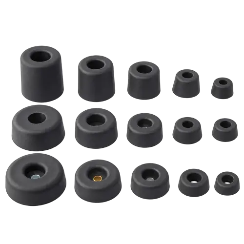
Foot, cup and bell housings earn their cost in two situations only: the machine must be leveled after installation, or the mount has to be replaced without lifting the machine off its anchors.
Swap a 25 mm tall mount for a 20 mm pad and the motor drops 5 mm relative to the pump. On a coupled set, that difference lands in the coupling, and the misalignment becomes a new vibration source that is often worse than the one you set out to fix. Measure the old part's loaded height, not its free height, and check the number against the coupling's alignment tolerance before you commit.
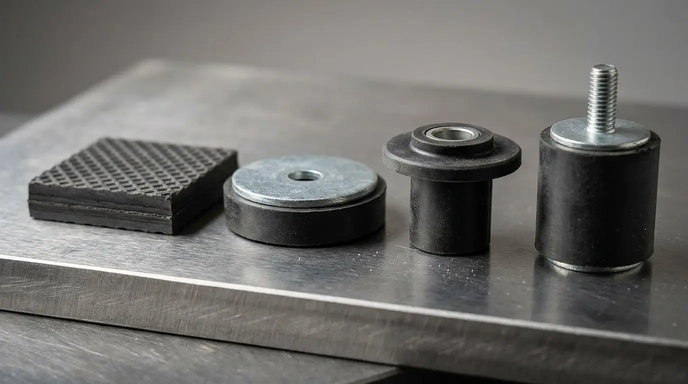
Rubber is strong in compression and weak in tension, and the weakness concentrates at the bonded edge. Load a bonded pad so it lifts, and a peel starts at the bond line and propagates across the face until the rubber separates cleanly from the metal. That is not a compound failure and no material upgrade will fix it. A pad that lifts is being asked to do something it was never shaped for.
A bushing loaded in shear gives a soft vertical rate with high lateral stiffness from the same moulding, because the rubber is being pushed sideways rather than squeezed. That combination is why pumps on driven shafts and machine tools sit on them: soft where the vibration lives, stiff where the alignment lives. A compression pad of the same diameter and height would be stiffer vertically, but its lateral resistance would come mainly from friction at the faces, or from shear if the rubber is bonded to a plate. That is a much smaller lateral rate than a bushing delivers, which is why the two forms are not interchangeable.
A studded mount on a motor sees vertical compression from weight, lateral shear from belt pull or torque reaction, and short bursts of tension at start-up and during transport. Rate the part for that combination. Steady-state weight covers only the compression side of the duty cycle, and it says nothing about the torque that rotates the machine about its own axis on every start. Because the mounts sit off that axis, the pair on one side compresses further while the pair on the other unloads and can lift almost completely, even though the machine's weight never changes direction. That lift is what puts the bonded edge into tension, and the bond line is where the peel begins.
An interlocked or captive mount lets the rubber deflect through its working range, then stops it from lifting or tearing past a set gap under shock. It is a mechanical travel limit, not a safety accessory. If you can lift the machine off its mounts by hand, the design has no retention and the rubber is the only thing holding it down.
Hardness by feel is how mounts end up amplifying the vibration they were bought to remove. Size from two numbers instead: load per mount, and the static deflection that puts the natural frequency where you want it.
Machine weight plus attachments, divided by the number of mounts, then an allowance for uneven sharing. Four mounts on an imperfect floor or a flexible frame never share equally, and the allowance you add should reflect how flat the floor is and how stiff the frame is, not a fixed percentage copied from a chart. The stiffest corner takes more than its arithmetic share, so sizing every mount at exactly one quarter of the total under-sizes the part that fails first.
This is the real design decision. Stiff mount, small deflection, high natural frequency, poor isolation. Soft mount, large deflection, low natural frequency, good isolation, more movement and a genuine need for snubbing and clearance checks around the machine.
Natural frequency in Hz is roughly 15.76 divided by the square root of static deflection in millimetres. A mount that settles 4 mm sits near 8 Hz. Turn the formula around and a target of 5 Hz needs about 10 mm of static deflection, which is a tall, soft, large-area part by definition. That single calculation tells you whether the shape you picked can do the job at all.
Transmissibility equals one when the forcing frequency is root two times the natural frequency, roughly 1.41 times. Below that ratio the mount is doing nothing useful, and close to resonance it amplifies. Keep the natural frequency at about a third or less of the lowest forcing frequency and you are safely past that boundary with margin for load changes.
Design against the lowest one, because that is the frequency the mount must be soft enough to isolate. This is also the honest limit of small mounts: geometry and available height cap deflection, so a short catalog part sometimes cannot solve a low-frequency problem no matter which durometer you pick.
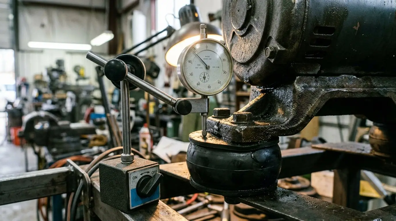
Two pads at 60 Shore A with different thicknesses are not interchangeable, and quoting hardness alone in an RFQ leaves the spring rate undefined. Stiffness comes from compound modulus, loaded area and free height acting together, and the shape factor ties them together.
A thin, wide pad has a high shape factor: the rubber cannot bulge sideways, so it behaves far stiffer in compression than the same compound in a tall, narrow block. Hardness is measured on a test button, which is a compound property, not a part property. Bonding a steel plate to one face changes the shape factor and the failure mode at the same time, because the rubber can no longer bulge or peel at that face.
This is a separate decision from stiffness, and it should be made after the geometry:
Hongjie moulds O-rings, seals and custom moulded rubber parts in NBR, FKM (Viton), EPDM, Silicone (VMQ), FFKM, HNBR, FVMQ (fluorosilicone), CR (neoprene), SBR, polyurethane (AU and EU), VAMAC (AEM) and XNBR, with access to 200+ proprietary rubber compounds. Compounds are rated from -60 degrees C to +325 degrees C for extreme environments, and chemical compatibility resistance testing covers 500+ fluids, gases and chemicals.
A compound with a wide temperature rating still takes permanent set if it is strained hard at high temperature for years. Design for the service temperature the mount actually lives at, not the peak it survives for an hour. A mount that sits at 90 degrees C continuously under load will flatten even if its datasheet claims 200 degrees C.
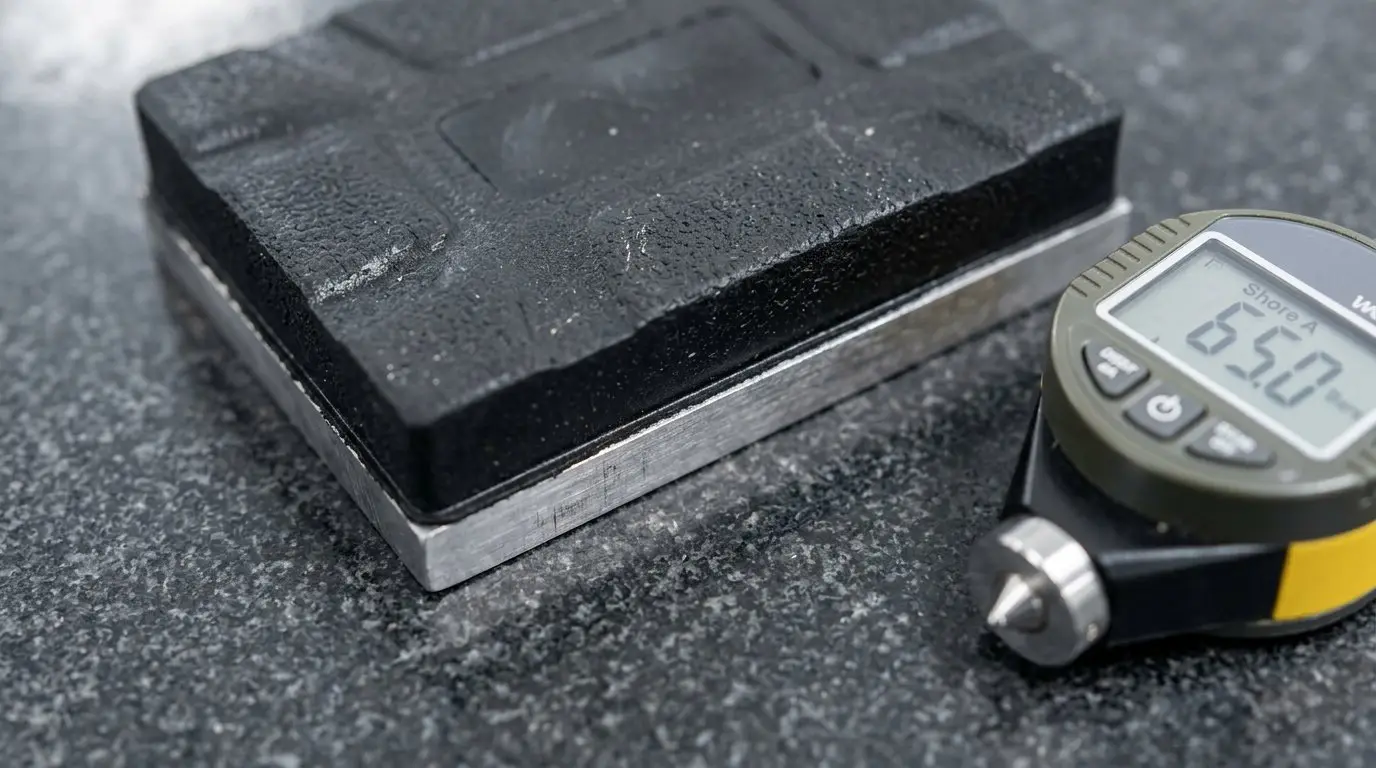
A mount that is right for the load and wrong for the bolt pattern is still the wrong mount. These are the numbers on your drawing that must match, and what each one breaks when it does not.
Tight dimensions matter here in a way that is easy to underestimate. Hongjie's precision moulding processes deliver tolerances down to plus or minus 0.02 mm, which is worth knowing when the mounting envelope is tight.
You can specify a perfect mount and install it so it behaves like a solid block. These are the assembly errors that show up most often, and each one has a mechanical reason behind it.
Take a plant that retrofits a 15 kW blower onto a lighter enclosure frame. The mounts are correct, the torque is correct, and the noise still goes up, because the frame now resonates where the old one did not.
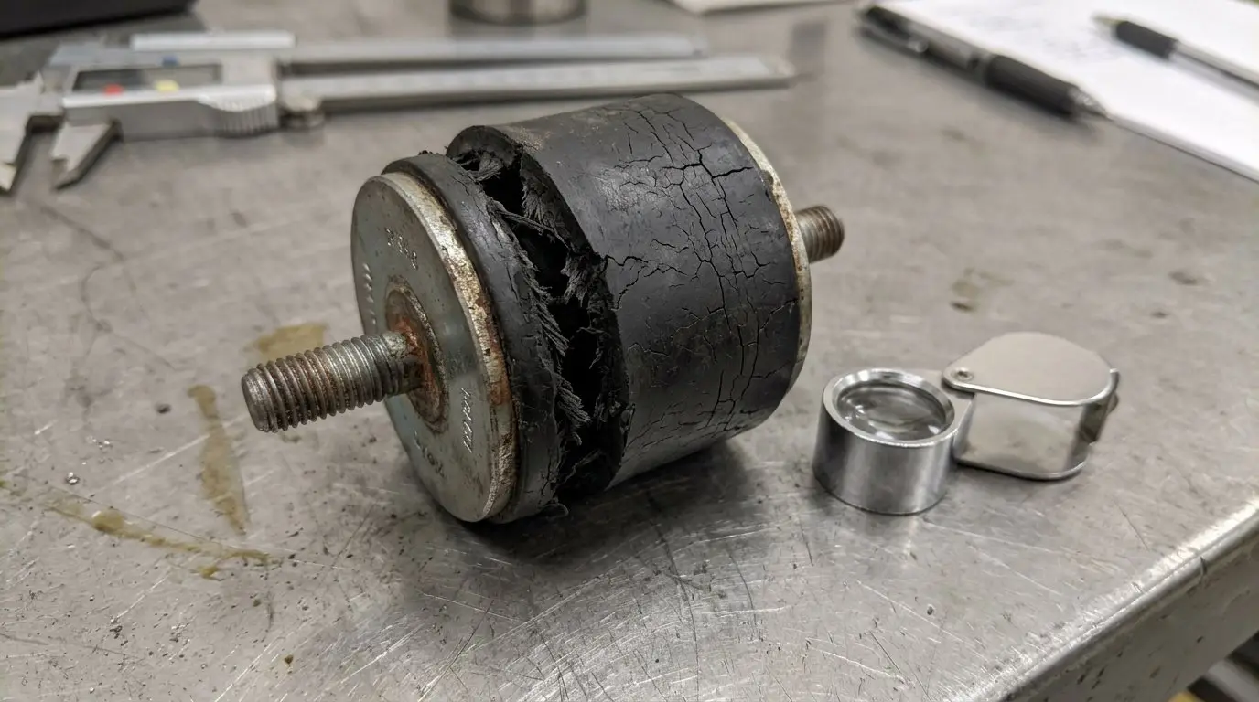
The part in your hand is a diagnostic record. The surface tells you whether the problem was form, sizing, compound or assembly, and the four categories have distinct signatures.
Fast failure within weeks points to the wrong form or an installation error. Slow failure over years points to compound choice or environment. That split alone often saves a round of guessing, and the same logic runs through our breakdown of rubber seal failure root causes.
Most quotes come back wrong because the enquiry described a shape instead of a function. Put these fields in the email and a moulder can quote the right part first time.
| Field | What to state |
|---|---|
| Load per mount | Newtons or kilograms, plus direction |
| Dynamic input | Machine mass and forcing frequency |
| Deflection target | Static deflection in mm or natural frequency in Hz |
| Interface | Pad, through-hole, tapped boss, stud gender |
| Envelope | Footprint, height, stack height limit |
| Thread | Size, pitch, length per end |
| Rubber | Compound, hardness with tolerance |
| Environment | Temperature range, fluids, UV, washdown |
| Retention | Snubbing, captive hardware, fail-safe requirement |
| Volume and paperwork | Annual quantity, inspection level, documents required |
That line on machine mass and forcing frequency matters more than it looks. It lets an engineer check whether the hardness you asked for can reach your deflection target in the space available, which is the check that prevents a sample round trip.
Ask for stiffness or load-deflection data with the sample, not just a durometer reading, so the part can be verified against the target rate on a test rig.
Custom moulding covers exactly that case. An existing standard profile may be reused from the 3,500+ standard profiles and existing tooling held for established sizes and geometries, or a new tool built for the geometry. Hongjie's team offers a 24-hour evaluation for custom-moulding specs and functional prototypes in as little as 3 to 5 business days, with production runs shipped within 15 to 20 business days.
State the quality requirement up front so inspection and paperwork are priced from the start: inspection options include AQL 1.0, 0.65, 0.15 or C=0, and documentation can include material records, dimensional inspection reports, control plans, sample records and PPAP-related files from an IATF 16949:2016 certified system.
Without a part number, the starting point is either the failed part or the drawing it has to fit.
If you are holding a failed isolator with no part number, work backwards through the failure signatures first. If you are holding a drawing with a mounting point no stock part will fit, the rubber engineering and mould design team can review the spec against existing tooling, and you can browse the custom rubber parts range to see the formats already in production. Send the drawing and the load figures through the contact page and you will get an evaluation rather than a part number guess.
Static stiffness is measured under a slow load, while dynamic stiffness is measured under oscillation and is normally higher, because rubber is viscoelastic and stiffens as the rate of strain rises. The gap widens with frequency and with filler content, so a mount sized from a static load-deflection curve can end up with a natural frequency above the target. Ask for the dynamic rate when the natural frequency matters.
Two identical pads in series do roughly halve the vertical rate, so the machine sits lower and softer. The trouble is everything else: the stack loses lateral stability, the top pad can walk, shear stiffness collapses, and the extra height changes the shaft centreline on a coupled set. A single taller, larger-area pad or a proper bushing is the better answer in almost every case.


Our engineering team reviews your specs and responds within 24 hours with material recommendations and competitive pricing.