An O-ring gland works only when four numbers line up correctly: squeeze between 15–30%, stretch under 5%, gland fill between 75–90%, and an extrusion gap tight enough to resist the system pressure. Get any one of these wrong and the O-ring itself is irrelevant — a perfect ring in a bad groove will still leak, extrude, or fail early. This guide walks through how to calculate each parameter and where engineers most often get the math wrong.
Here's an uncomfortable truth: most O-ring failures blamed on “bad material” or “bad batch” are actually gland geometry problems. We've covered the broader failure patterns in why rubber O-rings keep failing, but gland design deserves its own deep dive because it's the one variable engineers control completely — before the ring even ships.
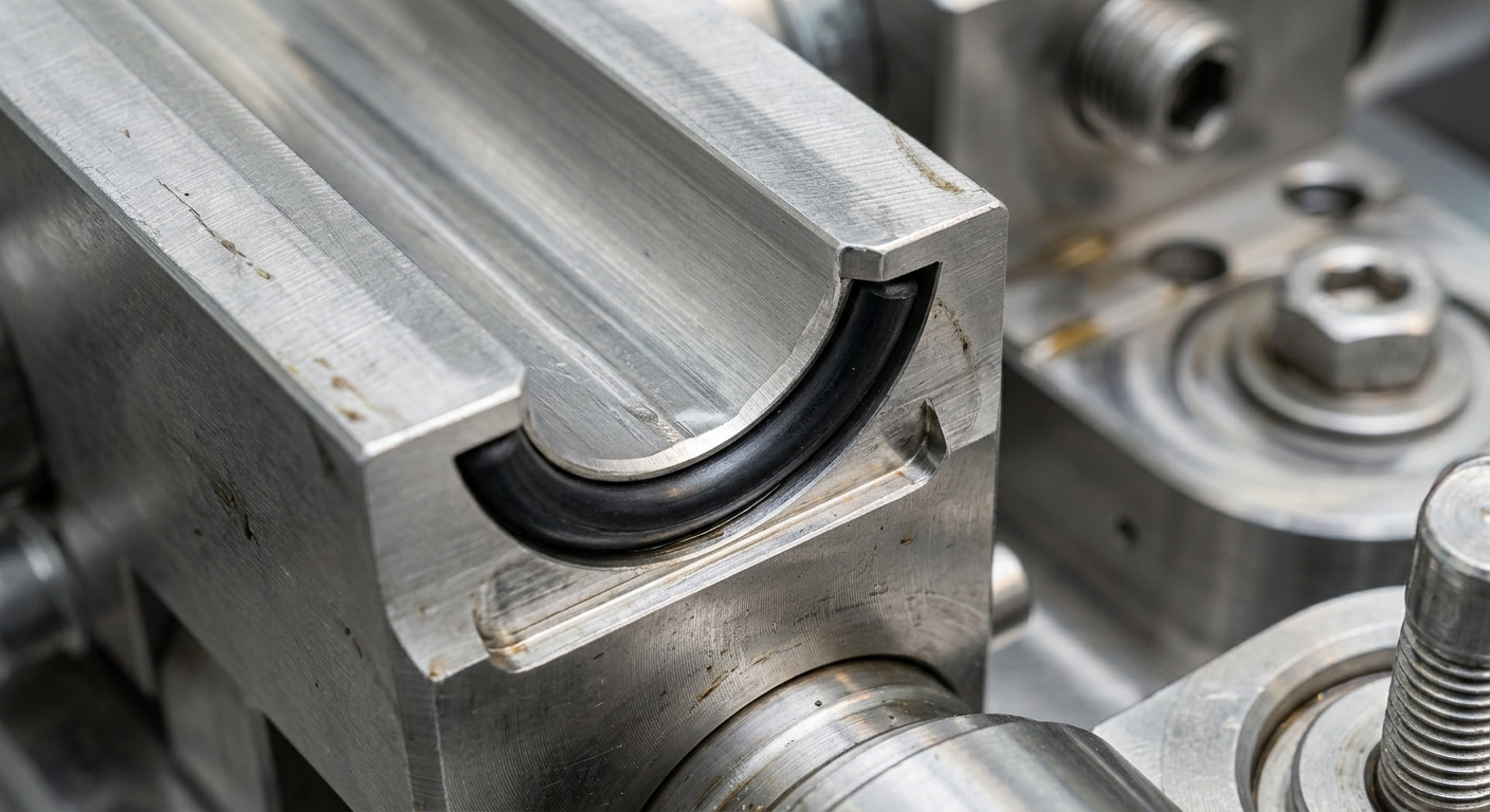
A gland is simply the machined cavity — groove width, groove depth, and bore or shaft diameter — that houses the O-ring and compresses it enough to create a seal. Design it too loose and the ring can't seal. Design it too tight and you'll destroy the ring on day one, either during installation or the first thermal cycle. The four variables below are not independent — change one and you often need to recheck the others.
Squeeze is the percentage compression of the O-ring's cross-section when installed. It's calculated as (Cross-Section Diameter minus Gland Depth) divided by Cross-Section Diameter, times 100. This compression is what generates the contact stress needed to block fluid or gas — no squeeze, no seal, full stop.
Static seals — flange gaskets, end caps, cover plates — can tolerate 15–30% squeeze because there's no relative motion wearing down the rubber. Dynamic seals — piston rods, rotating shafts — should stay closer to 10–20%. Push squeeze too high on a dynamic seal and you're just manufacturing friction and heat, which accelerates compression set and shortens service life fast.
Engineers sometimes copy a squeeze percentage from a datasheet without checking the durometer. A 70 Shore A FKM ring behaves very differently under 25% squeeze than a 90 Shore A HNBR ring — harder compounds need less squeeze to achieve the same sealing force, and pushing high squeeze on a hard compound risks cracking during installation. For instance, a hydraulic cylinder manufacturer switching from NBR 70 to a harder 90 Shore polyurethane for higher pressure service had to redesign the gland depth, not just swap materials, because the original 22% squeeze was too aggressive for the stiffer compound.
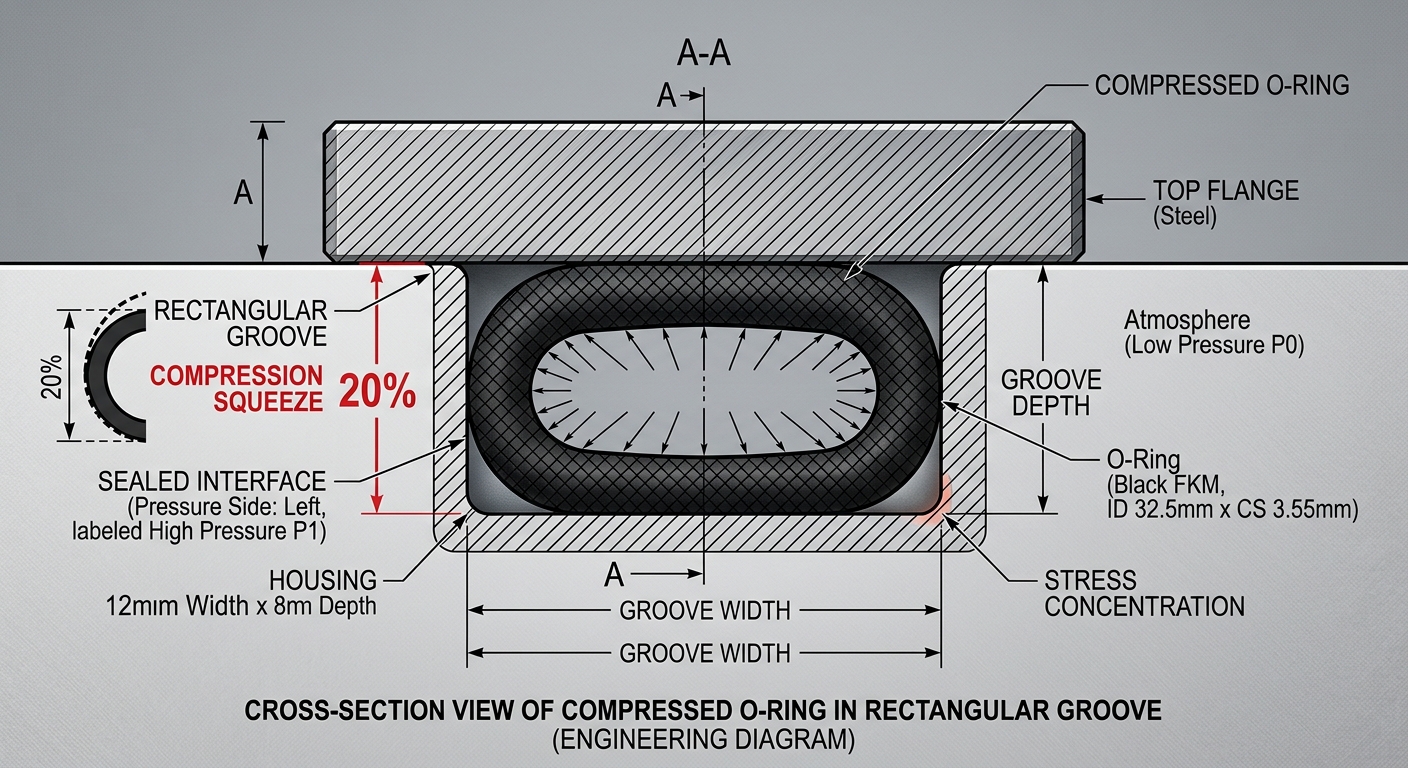
Stretch refers to how much the O-ring's inner diameter is expanded when installed over a shaft or into a bore, expressed as a percentage increase from its relaxed ID. For most applications, target 1–5% stretch — enough to keep the ring seated and stable during handling and assembly, but not so much that you thin out the cross-section and weaken the seal.
Why does stretch matter beyond just installation? Because stretching an O-ring reduces its cross-sectional diameter slightly, which in turn reduces your effective squeeze. If you stretch a ring 8% instead of the planned 3%, your actual squeeze percentage drops below what you calculated on paper — and now you have a marginal seal that looks fine in CAD but leaks in the field.
On rotary applications, excessive stretch also increases running friction and generates heat at the seal interface. If your design calls for more than 5% stretch just to make assembly easier, it's usually a sign the groove ID needs to be resized rather than compensated for with stretch.
Gland fill is the percentage of the total groove volume occupied by the O-ring's cross-sectional volume. Target range: 75–90%. This one gets overlooked constantly because squeeze and stretch feel more “important,” but gland fill is what prevents two very different failure modes.
The O-ring has room to float, roll, or twist inside the groove — especially under vibration or pressure pulsing. A loose-fitting ring in an oversized groove is a common cause of intermittent leaks that pass initial testing but fail after a few thousand pressure cycles.
This is the more dangerous mistake. Rubber expands with temperature — roughly 1–2% volumetric expansion per compound depending on the elastomer. If the groove is already near 90% full at room temperature, thermal expansion in a hot hydraulic system or engine bay can push the ring toward hydraulic lock, where it has literally nowhere to go. The result is groove damage, extrusion, or a ring that gets crushed against the metal walls hard enough to tear.
A practical example: a manufacturer producing seals for engine coolant systems originally speced 92% gland fill using standard NBR. Once coolant temperatures pushed the compound near its upper working range, thermal expansion caused seal extrusion failures within weeks. Dropping gland fill to 82% and switching to EPDM — which handles coolant chemistry better — solved both problems at once.
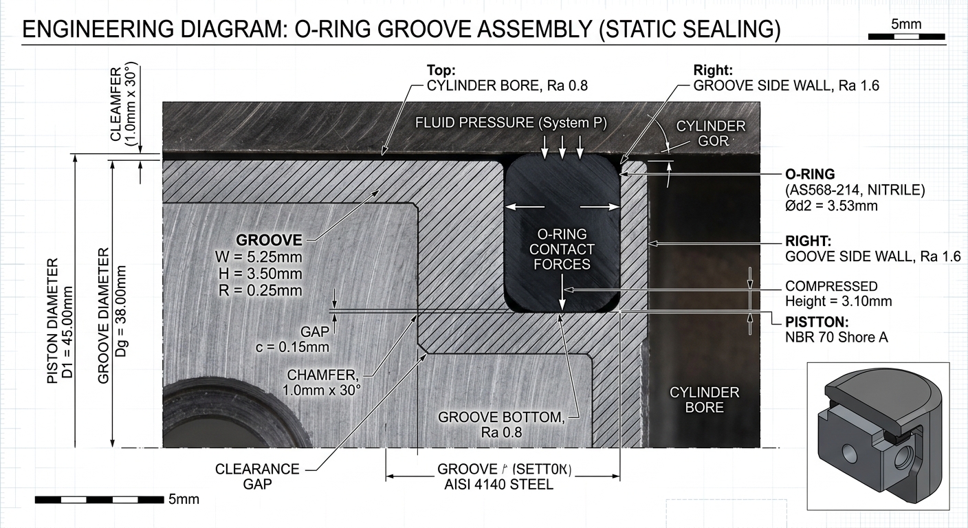
The extrusion gap is the diametral clearance between the two mating metal surfaces the O-ring seals against — piston and bore, or rod and gland. Under pressure, the O-ring wants to flow into this gap. If the gap is too wide relative to system pressure and the ring's durometer, you get extrusion: small tongues of rubber get pushed (or nibbled, under cyclic pressure) into the clearance until the seal fails.
For standard 70 Shore A compounds at moderate pressure (under 1500 psi), keep diametral extrusion gaps under 0.005 inch. As pressure climbs into the 3000–5000 psi range, that gap needs to shrink further, or you need to move to a harder durometer (90 Shore A) or add anti-extrusion backup rings.
Extrusion gap problems show up most in hydraulic and pneumatic cylinders where manufacturing tolerances stack up across multiple machined parts. A gap that's fine on paper can widen in the field due to bore wear, thermal expansion mismatches between aluminum and steel components, or eccentricity from misaligned assembly. This is exactly the kind of issue worth reviewing during engineering review before tooling is cut, not after parts are already failing in the field.
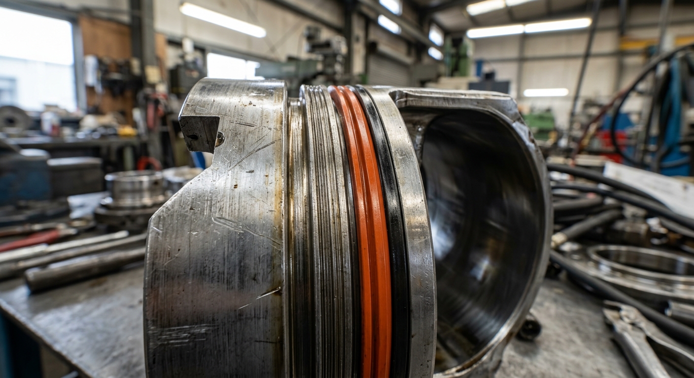
None of these numbers exist in isolation. Consider a static flange seal at 3000 psi using a 3.53mm cross-section 90 Shore A FKM O-ring. If you push squeeze to 28% to guarantee sealing (fine on paper), but the groove was cut slightly oversized, your actual gland fill drops to 70% — below the safe range. Now the ring has room to shift under pressure pulsing, and combined with a wider-than-spec extrusion gap from bore tolerance stack-up, you get intermittent extrusion failures that look random on the production floor but are entirely predictable from the geometry.
This is why gland design should always be checked as a system, not four separate boxes to tick. A change in cross-section diameter to fix squeeze will shift gland fill. A change in groove width to fix gland fill will change squeeze. Get the sequence right: set squeeze first based on application type, then verify gland fill falls in range, then check stretch for installation, and finally confirm extrusion gap against your actual operating pressure — including pressure spikes, not just steady-state.
Squeeze and extrusion targets aren't universal constants — they shift with the compound. Softer materials like 50–60 Shore A silicone need more squeeze percentage to generate equivalent sealing force but tolerate extrusion poorly, so they need tighter gaps. Harder compounds like 90 Shore A HNBR or FFKM can run tighter extrusion gaps at high pressure and lower squeeze, but risk cracking if squeeze is pushed too aggressively during cold-temperature installation.
For chemically aggressive environments — think oil and gas or aggressive cleaning chemicals in drinking water systems — material selection and gland geometry have to be solved together. A compound with poor chemical resistance can swell in service, which changes your gland fill calculation entirely; a ring that starts at 80% fill can swell to 95%+ after prolonged fluid exposure and lock itself into the groove. This is one more reason material compatibility testing needs to happen before gland dimensions are finalized, not after.
On paper, gland design is arithmetic. In practice, it's a conversation between the ring geometry, the metal tolerances, the operating temperature range, and the fluid or gas being sealed. That's why experienced sealing manufacturers run squeeze, stretch, gland fill, and extrusion gap calculations against real tolerance stack-ups — not just nominal dimensions — before committing to tooling.
If you're developing a new sealing application, whether it's a hydraulic cylinder, a medical device housing, or a plumbing fitting, it's worth reviewing your O-ring and custom rubber seal options against the actual gland geometry early, rather than after parts are already in production.

Our engineering team reviews your specs and responds within 24 hours with material recommendations and competitive pricing.