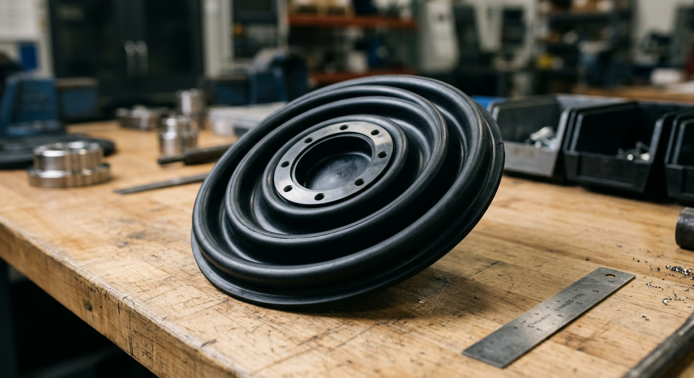
A rubber diaphragm fails when its material chemistry, hardness, or flex geometry doesn't match the real cyclic stress it faces — not because rubber is inherently unreliable. Get the material right for the media, the hardness right for the deflection, and the convolution profile right for the stroke, and a well-made diaphragm can handle millions of cycles without cracking. Get any one of those three wrong, and you'll be replacing diaphragms every few months no matter how good the rest of the pump is.
Here's an uncomfortable truth: when a diaphragm splits after six months instead of the expected five years, engineers almost always blame the rubber batch first. In our experience running molded rubber production, the batch is rarely the problem. The design is.
A diaphragm doesn't just seal — it flexes thousands or millions of times, bending along the same stress line over and over. If that stress line sits on a flat, uniform-thickness disc instead of a properly engineered convolution, you're asking the rubber to fold on itself in the same spot every single stroke. That's a fatigue crack waiting to happen, usually within a few hundred thousand cycles.
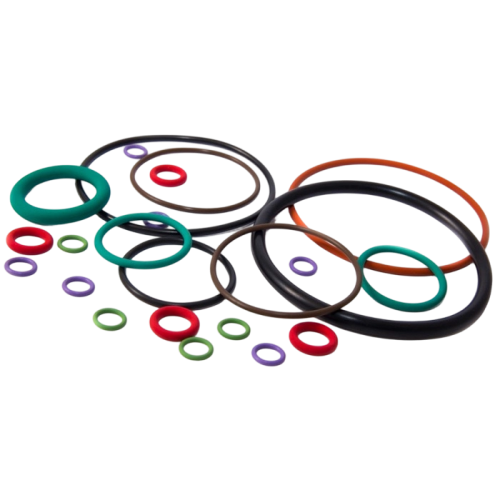
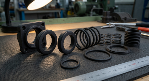
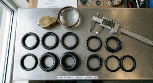
This is the same failure logic we cover in our piece on why rubber O-rings keep failing — most sealing failures trace back to a mismatch between the part's geometry and its actual operating stress, not a bad rubber compound.
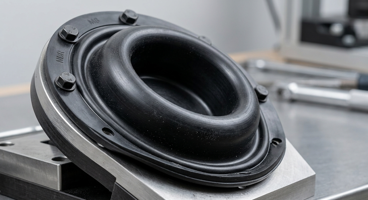
Pick the wrong elastomer and no amount of geometry tuning will save the part. Media compatibility comes before everything else in diaphragm design.
EPDM is the workhorse for drinking water systems, steam applications, and mild chemical exposure. It resists ozone, UV, and polar fluids well but swells badly in petroleum oils — so never spec it for a fuel or hydraulic diaphragm.
Nitrile rubber handles mineral oils, fuels, and hydraulic fluids reliably up to about 100C. It's the standard choice for automotive fuel pump diaphragms and many hydraulic control valve diaphragms.
Silicone has outstanding fatigue resistance and a huge temperature window (-60C to 200C), which makes it ideal for medical dosing pumps and appliance diaphragms that flex constantly. It's weak against fuels and many solvents, though, so don't use it where hydrocarbon exposure is likely.
When a diaphragm valve handles acids, fuels, or high-temperature process gases, FKM earns its higher price tag. It's stiffer and has lower flex fatigue life than silicone, so geometry compensation matters more here.
For a full rundown of material properties across our catalog, see our rubber parts product range.

A common mistake: specifying the softest rubber available because 'flexible = durable.' That logic breaks down fast in real pumps.
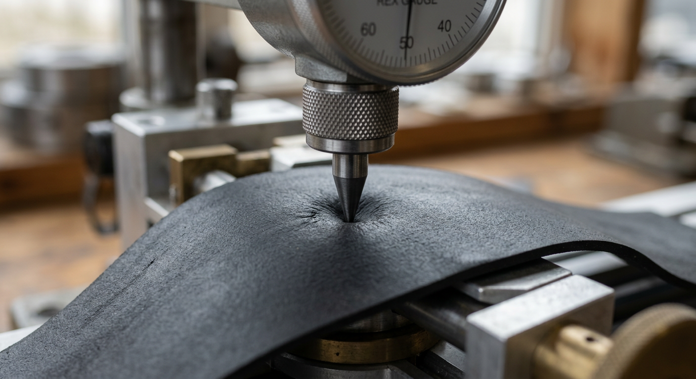
Too soft (below 40 Shore A) and the diaphragm can buckle, flutter, or extrude into valve seats under pressure — especially in reciprocating pumps with high discharge pressure. Too hard (above 80 Shore A) and you get high bending stress concentrated at the flex radius, which shortens fatigue life dramatically.
Our general rule for most pump and valve diaphragms: 50-70 Shore A covers the sweet spot for balancing flexibility with pressure resistance. For low-pressure metering pumps, 40-55 Shore A gives smoother deflection. For high-pressure diaphragm valves handling 10+ bar, 65-75 Shore A resists extrusion better while still flexing cleanly within a properly designed convolution.
A chemical dosing equipment maker once came to us with a silicone diaphragm failing after only 200,000 cycles at 45 Shore A — it was ballooning under back-pressure and fatiguing at the edges. Switching to 60 Shore A silicone with a reinforced fabric backing pushed cycle life past 2 million without changing the pump's stroke length.
The shape of a diaphragm determines how it distributes bending stress — and this matters more than most spec sheets suggest.
Simple to mold and cheap, flat discs work fine for low-stroke, low-cycle applications like pressure-relief valve diaphragms or one-shot actuator seals. Push them into a continuous-duty pump and they fatigue at the clamp edge quickly.
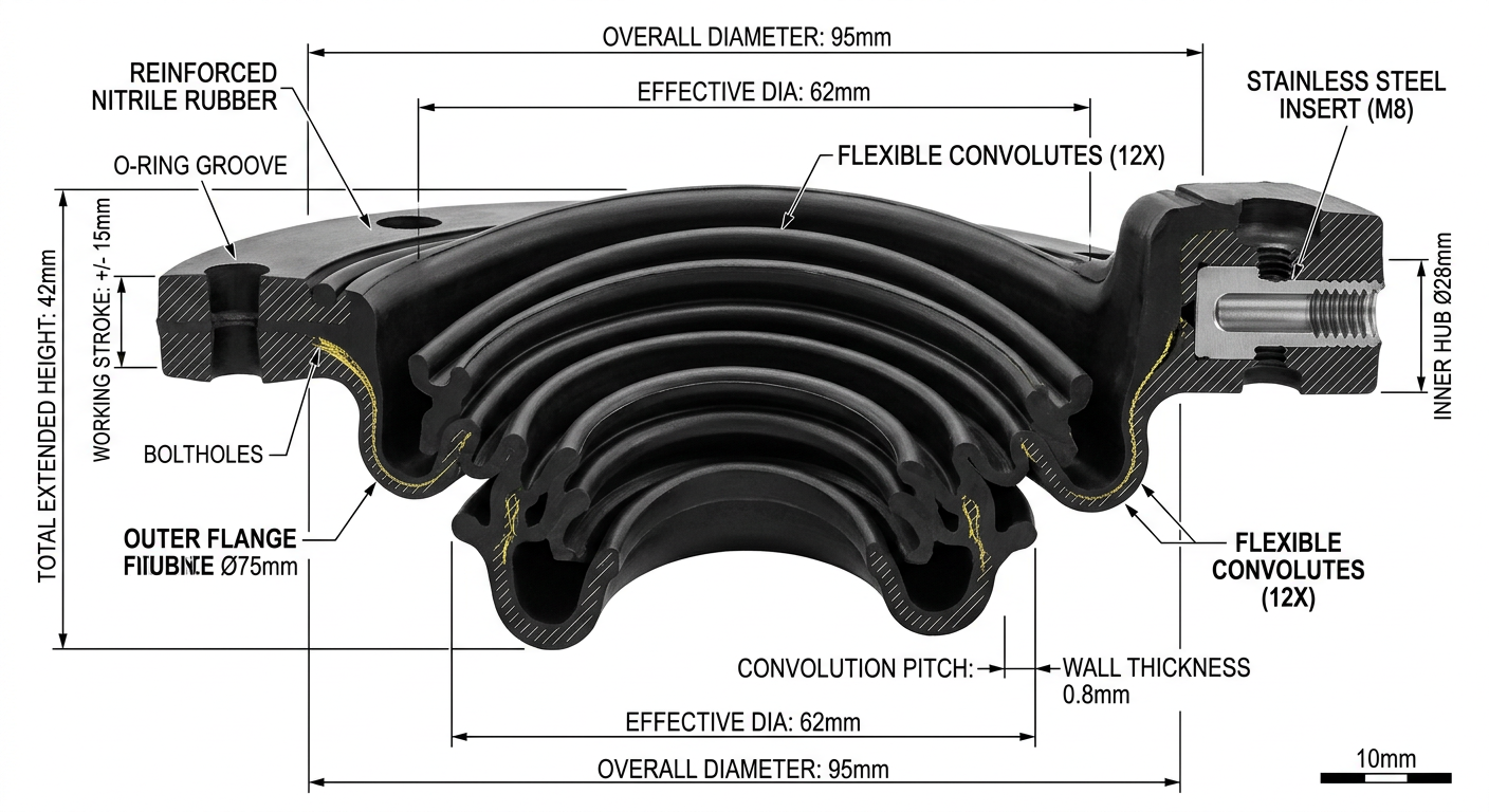
A single or double convolution lets the diaphragm roll rather than stretch during the stroke. This spreads bending stress across a wider radius instead of concentrating it at one crease. For reciprocating pumps with strokes over 5mm, a convoluted profile is almost always the right call — it's the difference between 300,000 and 3 million cycle life in similar applications we've produced.
For high-pressure valve diaphragms, embedding a fabric layer (polyester or nylon mesh) between rubber layers controls stretch and prevents ballooning without stiffening the flex zone. This is standard practice for industrial diaphragm valves above DN50.
Wall thickness matters too — most functional diaphragms run 0.8mm to 3mm depending on pressure and diameter. Thinner sections flex easier but sacrifice pressure resistance; thicker sections need a wider convolution radius to avoid stress buildup.
Treating a pump diaphragm and a valve diaphragm the same way is a common OEM sourcing mistake — they experience fundamentally different loads.
Pump diaphragms undergo continuous, high-cycle flexing (often 60-300 strokes per minute, running 24/7 in industrial dosing setups). Fatigue resistance and convolution geometry dominate the design decision here.
Valve diaphragms mostly hold a static sealed position and only flex occasionally to open or throttle flow. For these, chemical resistance and pressure holding capability matter more than flex-fatigue life — a flat or lightly convoluted profile with a stiffer compound (65-80 Shore A) often performs better than a soft, highly flexible one.
For instance, a water treatment plant using pneumatically actuated diaphragm valves needs an EPDM diaphragm rated for constant water immersion and occasional full-stroke actuation — not the same spec as a chemical metering pump running continuously at 120 strokes per minute.
A diaphragm that looks correct on paper can still fail if the mold tooling doesn't control wall thickness uniformity. Uneven wall thickness — even a 0.2mm variation across the flex zone — creates a weak point that cracks long before the rest of the part wears out.
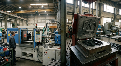
Compression molding and transfer molding both work for diaphragms, but transfer molding generally gives tighter thickness control on thin-wall convoluted profiles, which is why we favor it for anything under 1.5mm wall thickness. Flash lines at the flex radius are another common defect — even minor flash can act as a crack initiation site under repeated flexing, so trimming quality at that specific zone deserves extra inspection attention.
Our engineering support process includes prototype flex-cycle testing before full production tooling, specifically to catch these geometry and thickness issues before they become a field failure.
If your application doesn't fit neatly into these categories, that's normal — most custom projects need a specific combination worked out with actual pressure, stroke, and cycle data rather than a generic chart.

Our engineering team reviews your specs and responds within 24 hours with material recommendations and competitive pricing.