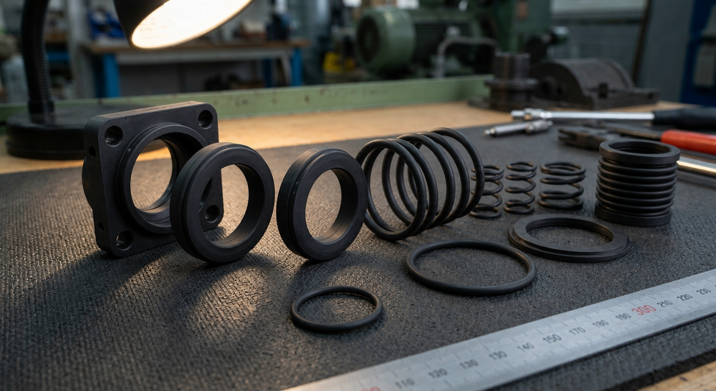
A sealing failure is rarely explained by one symptom alone. Leakage may come from the seal material, groove design, installation method, mating surface, pressure, temperature, contamination, lubrication or the equipment surrounding the seal. Replacing the damaged part without identifying that root cause often leads to the same failure again.
This guide covers static rubber seals, O-rings, gaskets, dynamic seals and mechanical face seals. Start with the visible damage, identify which sealing system failed, then work backward through material compatibility, geometry and actual operating conditions.
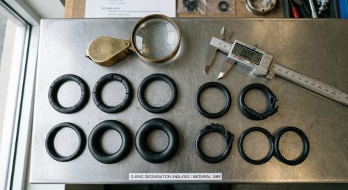
The condition of a removed seal can provide useful clues before laboratory testing begins. Use the table below as a starting point rather than treating any single symptom as definitive proof of one cause.
| Observed Failure | Likely Causes | What to Check First |
|---|---|---|
| Seal is swollen, soft or sticky | Chemical incompatibility or fluid absorption | Fluid, additives, cleaning agents and elastomer compound |
| Seal is hard, brittle or cracked | Excessive temperature, aging or chemical attack | Actual temperature history and material rating |
| Seal stays permanently flattened | Compression set or excessive squeeze | Groove depth, compression and temperature |
| Edges look torn or nibbled | Extrusion through excessive clearance | Pressure, extrusion gap and gland geometry |
| Cuts or missing pieces appear after assembly | Installation damage | Chamfers, sharp edges, tooling and lubricant |
| One side shows concentrated wear | Misalignment, eccentricity or uneven loading | Shaft, bore, housing and mounting alignment |
| Polished tracks or abrasion appear | Friction, contamination or rough mating surface | Lubrication, surface finish and particles |
| O-ring looks twisted or spiraled | Dynamic friction, poor lubrication or incorrect installation | Groove design, stretch and reciprocating motion |
| Mechanical seal face is cracked or heat-damaged | Dry running, inadequate cooling or thermal stress | Seal chamber condition and lubrication |
| Mechanical seal has uneven face wear | Runout, distortion, misalignment or vibration | Shaft, bearings, gland and equipment condition |
“Seal failure” can describe several very different problems. A static gasket, reciprocating O-ring and pump mechanical seal do not fail in exactly the same way, so the first troubleshooting step is identifying the sealing mechanism.
Static seals remain compressed between mating components. Common failure modes include compression set, chemical swelling, thermal degradation, extrusion, insufficient compression and installation damage. If you are troubleshooting an O-ring specifically, see our detailed guide to rubber O-ring failure root causes.
Dynamic seals must maintain contact while a shaft, piston or other component moves. Friction, lubrication, mating-surface finish, eccentric movement, contamination and seal geometry therefore become much more important than in a purely static joint.
Mechanical seals use rotating and stationary faces together with secondary sealing elements such as O-rings. Their failure analysis must consider both the seal itself and the equipment around it, including lubrication, cooling, shaft condition, alignment, vibration, pressure and the seal support system.
Chemical incompatibility is one of the easiest sealing problems to misdiagnose. A seal may initially fit correctly but gradually swell, soften, shrink, harden or lose mechanical strength after exposure to the operating fluid.
Do not select an elastomer only by generic material name. Actual compatibility depends on the compound formulation, fluid concentration, additives, temperature, pressure and exposure time.
| Material | Common Strengths | Important Selection Considerations |
|---|---|---|
| NBR | Petroleum oils, lubricants and general industrial sealing | Check temperature, fuel composition and aggressive chemical exposure |
| EPDM | Water, weathering, ozone and selected steam applications | Generally unsuitable for petroleum oils and fuels |
| HNBR | Oil resistance, improved heat resistance and refrigeration applications | Verify refrigerant and lubricant compatibility |
| FKM | Fuels, oils, heat and many chemicals | Not universally suitable for every hot-water, steam or chemical service |
| Silicone | Wide temperature range, flexibility and clean applications | Abrasion and dynamic wear may limit some applications |
| FFKM | Severe chemical and high-temperature environments | Compound selection and project cost require careful review |
ASTM D471 immersion testing, supplier compatibility data and application-specific validation can help confirm whether a compound is suitable. For projects requiring different compounds, sizes or hardness levels, review our standard and custom O-ring seals.
An elastomer needs enough elastic recovery to continue pressing against the sealing surfaces. When a removed gasket or O-ring remains permanently flattened, it may have developed excessive compression set.
Possible contributors include prolonged heat exposure, an unsuitable compound, excessive compression, long service time or a groove that does not allow the seal to deform correctly.
Extrusion occurs when pressure pushes elastomer into the clearance between mating components. Repeated pressure loading can tear away the extruded material, producing the characteristic rough or “nibbled” edge.
High pressure alone is not always the root cause. An excessive extrusion gap, soft compound, elevated temperature, pressure cycling or dimensional movement can all contribute.
Hydraulic applications deserve particular attention because pressure, clearance and dynamic movement interact. See our hydraulic O-ring seals page when specifying O-rings for hydraulic sealing positions.
A correct material cannot compensate for a badly designed sealing cavity. The groove must give the seal enough compression to establish contact while also providing space for deformation, thermal expansion and fluid-related volume change.
Problems can appear when the groove is too deep, too shallow, too narrow or excessively wide. Groove corners, tolerances, stretch and gland fill also affect performance. For O-ring applications, dimensions should be reviewed against the relevant design standard and the actual operating conditions rather than copied from an unrelated assembly.
A seal that leaks immediately after assembly should always be checked for installation damage before material aging is blamed. Cuts, scratches and local chunks missing from a new seal often point directly to the installation process.
When chronic leakage begins immediately after assembly but different batches show the same problem, review the installation fixture and housing geometry before assuming there is a molding defect.
Particles between the seal and mating surface can cut elastomers, wear dynamic sealing lips and damage mechanical seal faces. Contamination may enter during assembly or develop during operation as equipment wears.
Look at both the failed seal and the fluid. Metal particles, process solids, degraded lubricant, scale or cleaning residue can explain repeated wear that a new seal alone will not solve.
Dynamic sealing interfaces generate friction. Without suitable lubrication, frictional heat and wear can increase rapidly.
For an O-ring or other moving rubber seal, poor lubrication may produce wear tracks, twisting or surface damage. For a mechanical face seal, loss of the lubricating fluid film can overheat and damage the faces.
When investigating a mechanical seal, check whether the seal chamber was properly filled, vented and supplied during startup. Also review process interruptions, vapor formation, loss of flow and any condition that could temporarily remove lubrication from the sealing interface.
Heat can harden elastomers, increase compression set, accelerate chemical reactions and change dimensions throughout the sealing assembly. A seal may therefore fail at a temperature that appears acceptable on a basic material chart if the actual application also includes aggressive fluid, pressure, movement or repeated thermal cycling.
Thermal failure can appear as hardening, cracks, loss of elasticity, discoloration or permanent deformation. In mechanical seals, overheating may also damage or distort the face materials.
The pressure written on the equipment specification is not necessarily the highest pressure the seal experiences. Startup, shutdown, fast valve movement, blocked flow, pressure pulsation and thermal expansion can produce transient conditions that are missing from the original specification.
Repeated extrusion on one side of an O-ring, unexplained face loading or failures concentrated around system transitions are reasons to review pressure history rather than relying only on a single gauge reading.
The seal is only one half of the sealing interface. A damaged shaft, bore, flange or housing can destroy otherwise suitable seals.
If multiple replacement seals develop damage in the same position, inspect the hardware at that exact contact point.
Dynamic sealing systems are particularly sensitive to movement that changes the contact load around the seal. Shaft runout, bent shafts, bearing wear, coupling misalignment, piping strain and equipment vibration can all create uneven seal loading.
Typical evidence includes one-sided wear, fretting, unusual polished bands, uneven mechanical-seal face contact or repeated failure despite installing the same replacement correctly.
In these cases, changing from one elastomer to another may only hide the real mechanical problem temporarily. Inspect the equipment before changing seal specifications.
Some sealing failures begin because the application no longer matches the original design data. Maintenance teams may change lubricants, cleaning agents, process fluids, temperatures, pressures or cycle rates without revisiting the seal specification.
Comparing the conditions at the time of failure with the conditions used during original seal selection is often more useful than simply comparing the old and new part numbers.
Mechanical face seals deserve a separate inspection because they combine precision faces, secondary elastomer seals and rotating equipment. Damage found on one component may have been caused by another part of the system.
| Mechanical Seal Evidence | Possible Cause | Inspection Direction |
|---|---|---|
| Overheated or cracked faces | Dry running or inadequate cooling | Startup, venting, seal chamber and support system |
| Scored faces | Abrasive contamination | Fluid cleanliness and filtration |
| Uneven contact pattern | Distortion, alignment or runout | Gland, shaft, bearings and mounting |
| Chipped face edges | Vibration, impact or distortion | Equipment condition and installation |
| Damaged secondary O-ring | Chemical attack, heat, extrusion or installation damage | Compound, groove and operating conditions |
| Repeated leakage after short service | System problem not corrected by seal replacement | Review full operating history |
For pump systems using seal support or flush arrangements, confirm that the selected arrangement matches the actual process conditions. API 682 provides widely used guidance for mechanical seals and support systems, but the appropriate configuration depends on the equipment, fluid and operating conditions.
Static rubber seals do not have mechanical seal faces or continuous shaft movement, so their failure analysis should focus more heavily on compression, material behavior, groove geometry and installation.
Volume increase usually points toward interaction between the elastomer and its environment. Check every fluid the seal contacts, including lubricants and cleaning chemicals rather than only the main process medium.
A seal that does not recover after removal may have lost elastic sealing force through compression set, heat exposure or long-term deformation.
Damage concentrated near the low-pressure side of a sealing gap commonly suggests extrusion. Review pressure, clearance, groove dimensions and compound hardness together.
Localized cuts are often associated with assembly or contact with a sharp hardware feature. Inspect the installation path before changing the seal material.
A seal that leaks on the first pressure test has a different diagnostic path from one that operated correctly for two years. Immediate sealing failure usually puts installation, dimensions and assembly condition near the top of the investigation.
A useful failure analysis should preserve evidence instead of beginning with a cleaned, discarded seal. The objective is to connect the physical damage with what the component experienced during service.
Photograph the seal as removed. Record its orientation and leakage location before cleaning it. Keep mating components available when possible.
Document whether the leak appeared immediately, gradually or after a particular event such as startup, shutdown, maintenance, overheating or a process change.
| Information | What to Record |
|---|---|
| Fluid | Exact medium, concentration and additives |
| Temperature | Normal, minimum, maximum and startup conditions |
| Pressure | Normal pressure plus known transient conditions |
| Motion | Static, rotary or reciprocating |
| Speed | Shaft speed or cycle rate where applicable |
| Lubrication | Assembly and operating lubricants |
| Seal | Material, hardness, dimensions and batch |
| Hardware | Groove, gap, surface condition and tolerances |
| Service Life | Time or cycles before leakage appeared |
| Recent Changes | Fluid, equipment, supplier, maintenance or operating changes |
Describe what is actually visible: swelling, flattening, cracks, cuts, abrasion, extrusion, twisting, discoloration, deposits or uneven wear. Avoid beginning with a conclusion such as “bad rubber.”
Check the failed part against a retained sample or drawing and measure the actual housing wherever possible. A seal manufactured correctly can still fail if the groove or mating component is outside the required tolerance.
This is where a root cause becomes more credible. Swelling combined with a recent fluid change points in a different direction from swelling with no process change. Uneven wear together with bearing vibration is more informative than either symptom alone.
If five design variables are changed simultaneously, it becomes difficult to determine which change corrected the problem. Prioritize the evidence, implement the most justified correction and validate it under representative service conditions.
| Symptom | Possible Root Cause | Corrective Direction |
|---|---|---|
| Immediate leakage after assembly | Cut seal, wrong size, contamination, poor groove or uneven assembly | Inspect installation and dimensions |
| Leak develops gradually | Wear, compression set, aging or chemical change | Review service history and material condition |
| Seal becomes larger | Chemical swelling | Verify material compatibility |
| Seal becomes brittle | Heat, aging or chemical degradation | Review compound and temperature |
| Seal is permanently flat | Compression set | Review squeeze, compound and heat exposure |
| Torn low-pressure edge | Extrusion | Check gap, pressure and hardness |
| Repeated abrasion | Rough surface, contamination or inadequate lubrication | Inspect mating surface and fluid |
| One-sided wear | Misalignment or eccentric motion | Inspect shaft, bore and bearings |
| Twisted O-ring | Spiral failure or assembly twist | Review lubrication, stretch and groove design |
| Mechanical seal overheating | Dry running or inadequate cooling | Review startup and seal environment |
| Repeated mechanical seal leakage | Equipment or operating problem | Analyze pump and support system |
Changing materials makes sense only when the failure evidence supports a material problem. Selecting a more expensive elastomer will not correct a sharp groove edge, excessive extrusion clearance or misaligned shaft.
Before changing compounds, define:
For general oil-resistant sealing, NBR may be appropriate. Water and weather applications often lead designers toward EPDM. FKM is frequently considered for fuels, oils, heat and demanding chemical environments, while HNBR is widely used where oil resistance and improved thermal performance are needed, including selected refrigeration applications.
For refrigeration and automotive AC projects, see our HNBR O-rings for automotive AC and HVAC. For projects where silicone is appropriate, review our silicone rubber O-rings.
Repeated failures are sometimes caused by trying to make a standard O-ring perform a job better suited to a different geometry.
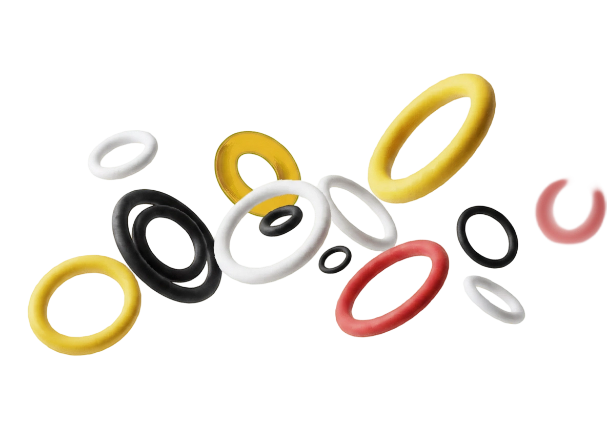
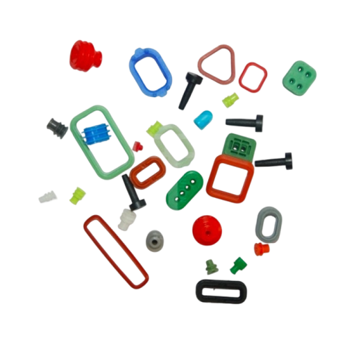
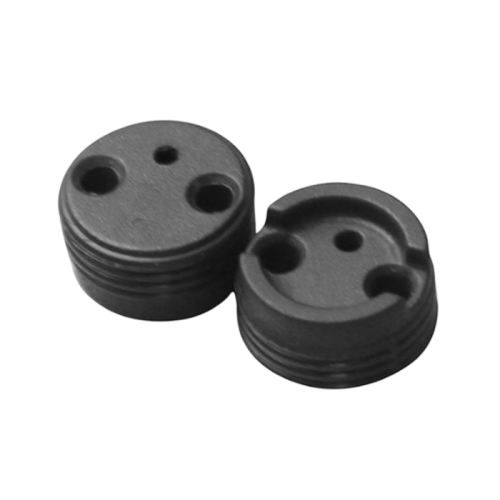
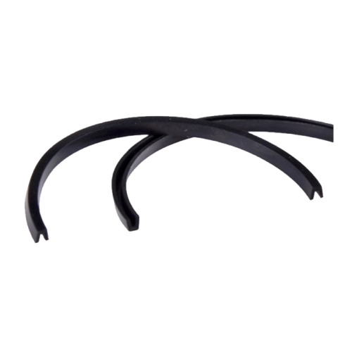
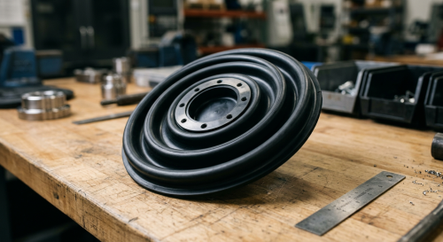
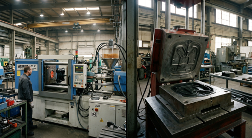
Hongjie manufactures custom rubber O-rings, molded rubber sealing gaskets and other custom rubber parts for applications where a catalog sealing component does not match the required geometry.
Most repeat failures become easier to prevent when seal selection, housing design and operating conditions are reviewed together rather than as separate issues.
If you are asking a seal manufacturer to investigate a repeated failure, “the O-ring leaks” is not enough information. A better technical package allows material, dimensions and application conditions to be reviewed together.
This information also helps determine whether the project requires only a different compound or a redesigned sealing component. Our engineering support team can review drawings, samples and service conditions for custom rubber sealing projects.
Common causes include chemical incompatibility, compression set, incorrect groove geometry, extrusion, installation damage, contamination, inadequate lubrication, excessive temperature, pressure spikes, poor mating surfaces, misalignment and changing operating conditions. The most likely cause depends on whether the seal is static, dynamic or a mechanical face seal.
Leakage is the most obvious sign, but failed seals may also show swelling, softening, hardening, cracks, permanent flattening, nibbled edges, cuts, abrasion, twisting, discoloration or uneven wear.
An O-ring can fail because of the wrong elastomer, incorrect squeeze, extrusion clearance, installation damage, compression set, abrasion, excessive temperature, contamination or dynamic twisting. The appearance of the failed O-ring should be compared with the groove and operating conditions before selecting a replacement.
Immediate leakage commonly points toward the wrong size, installation damage, contamination, insufficient compression, an incorrect groove, a scratched mating surface or uneven assembly. Long-term aging is less likely when the seal has never operated correctly.
Mechanical seal failures can result from dry running, contamination, incorrect material selection, poor installation, face distortion, inadequate cooling, pressure changes, shaft runout, bearing problems, misalignment or vibration. The condition of the pump and seal support system should be inspected together with the failed seal.
Yes. An assembly or operating lubricant can interact with some elastomers and cause swelling, softening or other property changes. Lubricant compatibility should therefore be checked together with compatibility with the primary process fluid.
Not automatically. Higher hardness may help in some designs, but repeated extrusion can also indicate excessive clearance, pressure spikes, temperature effects or an unsuitable groove. Correct the underlying geometry and operating problem before treating hardness as the only solution.
Preserve the failed seal, document the leakage location and service history, inspect the physical damage, confirm material compatibility, measure the groove and mating surfaces, review actual temperature and pressure data, and check the surrounding equipment. Corrective action should follow the evidence rather than simply replacing the same seal again.
A failed seal should be treated as evidence, not just as a worn part. Swelling points toward a different investigation than extrusion. One-sided abrasion raises different questions from compression set. Mechanical-seal face damage requires a different diagnostic path from a static gasket leak.
The most reliable approach is to connect three things: what the failed seal looks like, how the sealing hardware is designed, and what the application actually experienced. Only then should you decide whether the corrective action is a new material, revised dimensions, improved installation, equipment maintenance or a different seal design.
If you are troubleshooting a repeated rubber sealing failure, send Hongjie your failed-part photos, drawing, fluid, temperature, pressure and service conditions. We can review whether the issue is better addressed through compound selection, dimensional changes or a custom molded sealing component.

Our engineering team reviews your specs and responds within 24 hours with material recommendations and competitive pricing.